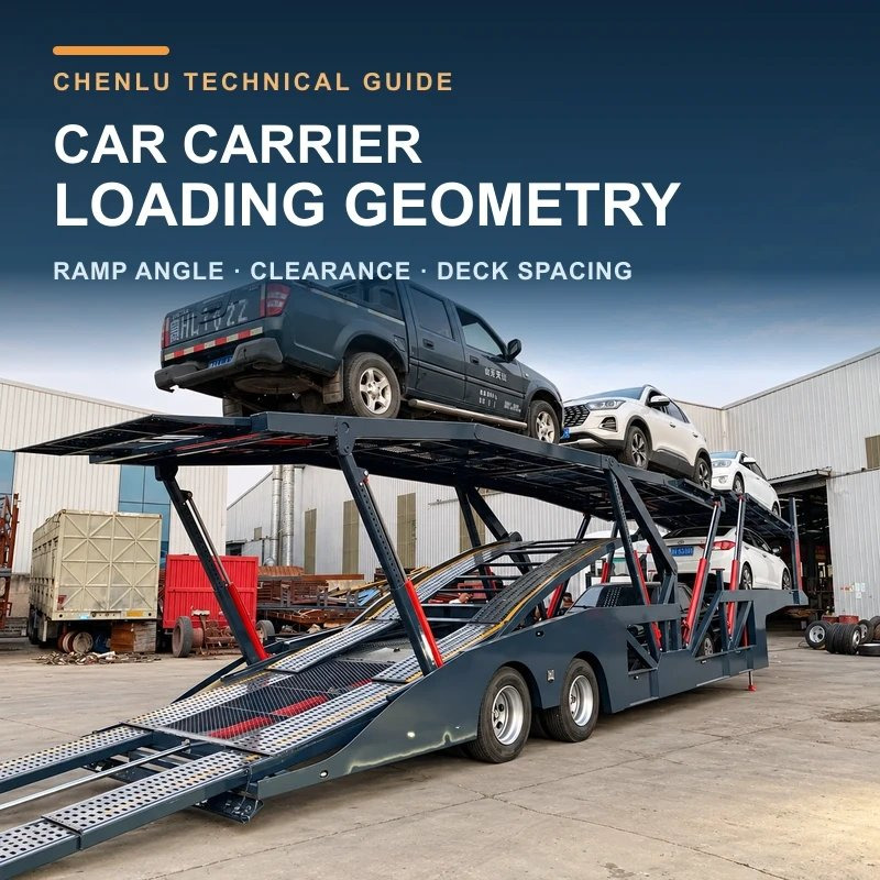
AI-assisted editorial cover based on a real CHENLU product photograph; it is not a model specification drawing.
To decide whether a sedan or SUV fits on a car carrier semi-trailer, assess the vehicle envelope, loading path and final transport position as one sequence. Check whether the front of the vehicle can enter the ramp, whether the underbody can cross the ramp crest or a deck transition, whether the roof can pass below the upper structure, and whether loaded height and load distribution remain suitable at the final position.
A low car may touch at the foot of the ramp or bottom out at the crest. A taller SUV usually climbs the ramp more easily but occupies more space between decks. Changing a deck angle may improve one condition while altering the next vehicle’s path, the final loaded height and the load distribution. A stated vehicle count describes one possible arrangement. Actual fit still depends on the vehicles in that arrangement.
Why Should Car Carrier Semi-Trailer Dimensions Be Checked Against the Actual Vehicle Mix?
Different vehicles expose different constraints first. Identifying the likely interference point before collecting the corresponding data is more useful than comparing only overall trailer length or a stated number of vehicle positions.
| Vehicle or transport condition | Check first | Why it matters |
| Low-ground-clearance car | Front overhang, front-lip height and transition at the ramp foot | The front may touch before the front tyres climb the ramp. |
| Long-wheelbase vehicle | Wheelbase, lowest point between the axles and the crest angle | The centre of the underbody may bottom out while the axles are on opposite sides of the transition. |
| Tall SUV | Actual vehicle height, parked angle and local deck clearance | The roof may approach the upper deck, a cross-member or hydraulic equipment. |
| Vehicle with roof accessories | Highest accessory and its longitudinal position | The stated vehicle height may not include a roof rack, antenna or another projection. |
| Heavier vehicle | Actual mass, centre-of-gravity basis and planned position | Its position changes the loads carried by the kingpin and trailer axle group. |
| Multi-stop unloading | Unloading order and every remaining arrangement | Removing one vehicle changes both deck access and the load case. |
Loading data can be grouped into three sets:
- Vehicle geometry: overall length, width and height; wheelbase; front and rear overhang; the height and longitudinal position of the lowest point; roof accessories and other projections.
- Mass and load data: actual kerb mass, carried accessories and any available centre-of-gravity information.
- Loading conditions: whether each vehicle can drive, steer and brake normally; loading-site conditions; tractor connection state; and the planned unloading order.
For example, “130 mm minimum ground clearance” still needs a position. A low point near the front axle, at the centre of the wheelbase or close to the rear reacts differently to the same transition. Aerodynamic parts, battery guards or exhaust components may also sit outside the manufacturer’s stated measurement point.
The CHENLU car carrier semi-trailer range covers the product category and available configuration direction.
A real CHENLU double-deck car carrier shown with a mixed vehicle arrangement. The photograph illustrates deck positions, not a fixed capacity for other vehicle combinations.
How Do Platform Height, Ramp Projection and Site Conditions Set the Ramp Angle?
Let h be the vertical rise and r the ramp’s horizontal projection. The average ramp angle is:
θ = arctan(h ÷ r)
Here, r is the horizontal projection, not the length measured along the ramp surface. Consider an independent example with a vertical rise of 0.80 m:
| Horizontal projection | Average ramp angle |
| 4.50 m | About 10.1° |
| 5.50 m | About 8.3° |
Increasing the horizontal projection by 1.0 m reduces the average angle by about 1.8°. A longer projection makes the ramp as a whole less steep, but the transitions from ground to ramp and from ramp to deck still need separate checks.
The actual loading path normally combines the site surface, rear ramps, tail deck and adjustable deck sections. The vehicle experiences the average slope along the ramp and a local change in angle at each connection. Ground slope, tractor fifth-wheel height, deck position and the way the ramp end bears on the ground all alter the path.
The 2022 Hyundai GLOVIS Transportation and Handling Manual recommends a maximum ramp angle of 7° within its own vehicle-handling system and also specifies several clearances. This shows how one operator may set defined limits for particular vehicles and procedures. The 7° figure is not a universal car-carrier design value. A CHENLU configuration still needs to be matched to its drawing, the actual vehicles and the site.
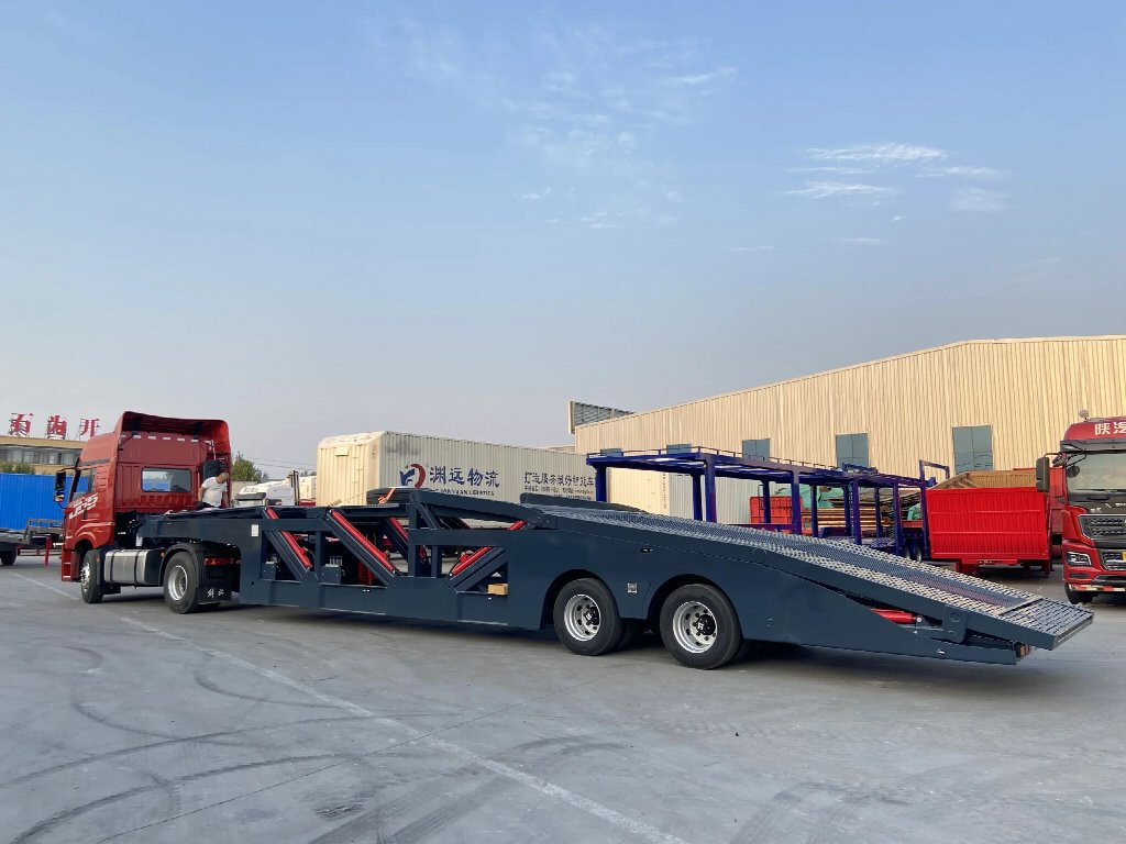
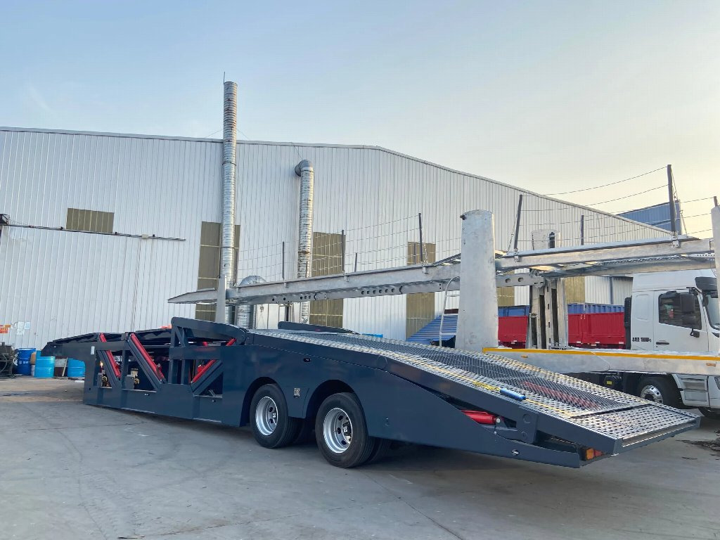
CHENLU car carrier in an unloaded configuration. The site surface, tractor connection and deck positions all form part of the loading path.
Why Can Vehicles With the Same Ground Clearance Have Different Loading Results?
A vehicle meets three different contact conditions as it moves along the loading path:
- Approach angle: whether the front and its overhang clear the ramp foot before the front tyres climb.
- Breakover angle: whether the underbody between the axles clears a convex transition while the tyres are on opposite sides.
- Departure angle: whether the rear and its overhang retain clearance as the rear tyres cross a transition.
The following breakover relationship is only an initial screen for an ideal convex transition. It treats the vehicle as a rigid body, places the front and rear tyre contact points on one reference plane, ignores tyre and suspension deflection, and uses one lowest point within the wheelbase.
Let c be the height of that point above the reference plane. Let a and b be the horizontal distances from its projection to the front and rear tyre contact points. The model gives:
β = arctan(c ÷ a) + arctan(c ÷ b)
If the lowest point is approximately at the middle of wheelbase W:
β ≈ 2 × arctan(2c ÷ W)
For a vehicle with a 2.70 m wheelbase and a 0.13 m central low point, the simplified result is about 11.0°. A convex transition near that order of magnitude calls for a closer underbody-clearance check.
The value is a geometric estimate, not a breakover angle approved by the vehicle manufacturer. Tyre and suspension movement, loading condition, uneven ground and unrecorded guards, exhaust parts or body accessories change the real margin. Two vehicles with the same minimum ground clearance may therefore behave differently because their wheelbases, overhangs and low-point positions differ.
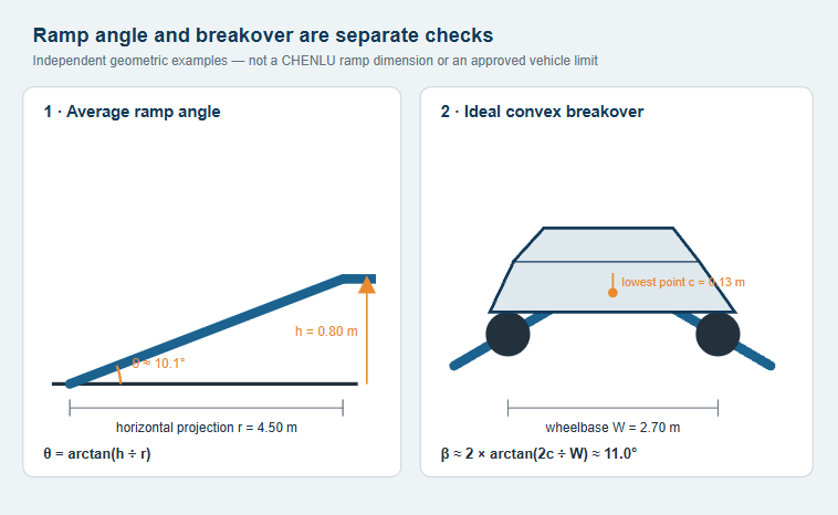
Independent geometric examples. The dimensions do not describe a CHENLU ramp or an approved limit for a specific vehicle.
How Should Clearance Between the Upper and Lower Decks Be Measured?
Clearance inside a double-deck car carrier is rarely one constant value. The upper deck may contain inclined and hinged sections. Cross-members, hydraulic equipment or other parts can project into the space below. When a vehicle sits on an inclined deck, the roof’s highest point also moves relative to the upper structure.
To avoid deducting the same obstruction twice, define three quantities at longitudinal position x:
- S₀(x): the base deck spacing from the lower vehicle-support surface to the upper reference plane, before local projections are deducted.
- I(x): the distance that a cross-member, cylinder or other structure projects from the upper reference plane into the deck space.
- Hᵥ(x): the vertical height of the vehicle envelope at that position, measured from the lower support surface with the vehicle at its actual parked angle.
M(x) = S₀(x) − I(x) − Hᵥ(x)
In an independent example, the base spacing is 1.72 m, a local structure projects by 0.06 m and the vehicle envelope at that position is 1.58 m:
M = 1.72 − 0.06 − 1.58 = 0.08 m, or 80 mm.
The 80 mm result is only a static arithmetic margin. The Hyundai GLOVIS manual cited above requires at least 4 in (about 102 mm) between the vehicle roof and the upper deck within its own scope. If that procedure applies, 80 mm does not meet its requirement. Other vehicles and operating systems need their own criteria; 102 mm is not a universal value.
Stated overall vehicle height is useful for screening. Final checks should follow the actual envelope of the roof, mirrors, roof rack, antenna and door frame. Clearance with an empty carrier does not establish clearance after every adjustable deck is placed in its transport position.
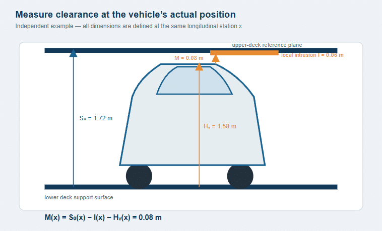
The calculation separates base spacing, local structural intrusion and the vehicle envelope so the same obstruction is not deducted twice.
How Do Adjustable Decks Change Loading Order, Vehicle Count and Loaded Height?
Deck position affects the ramp path, clearance between decks and the final vehicle envelope at the same time. Lowering one section may improve entry for one vehicle while reducing roof space at an adjacent position. Raising the upper deck releases lower-deck clearance but may increase loaded height. Vehicles already in place may also restrict later deck movement.
The published CHENLU two-axle double-deck car carrier semi-trailer is 16.12 m long and uses upper platforms with adjustable height and angle, together with rear loading ramps. Its product page shows two examples:
| Published CHENLU example | Vehicle mix | Loaded height stated on the page |
| Layout A | 5 sedans | 4,000 mm |
| Layout B | 3 SUVs + 1 sedan | 3,921 mm |
These rows describe different vehicle mixes. They are not a controlled comparison using the same vehicles with only the deck positions changed. The vehicle counts and loaded heights illustrate layouts published for that model; they do not promise fixed capacity for other sedan or SUV combinations. Actual results depend on vehicle length, height, mass, parked angle and deck position. Loaded-height measurement and tractor connection state should be confirmed from the drawing for the intended configuration.
Loading order belongs in the layout. If one vehicle must cross an adjustable section that another vehicle already occupies, the sequence has to change. Multi-stop unloading also needs checks for the remaining vehicles and deck positions after each removal. A full-load drawing represents one moment, not every intermediate state.
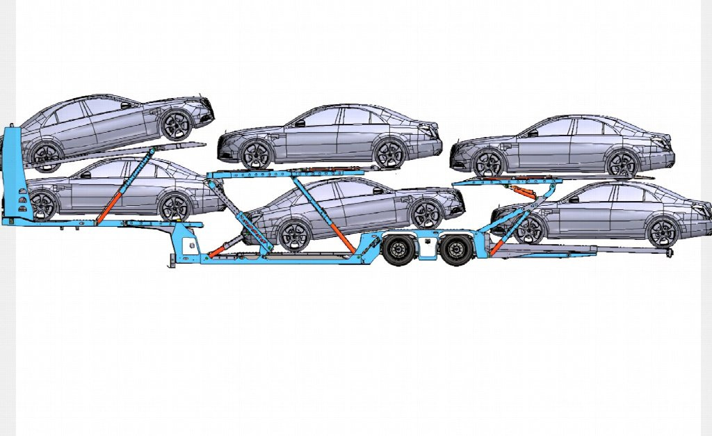
Published CHENLU five-sedan example. A different vehicle mix requires a new layout and load check.
How Does Vehicle Position Affect Car Carrier Trailer Weight Distribution?
A position that is geometrically available may still produce an unsuitable load distribution. A first static comparison can treat the semi-trailer as supported at the kingpin and the equivalent centre of the trailer axle group.
Let L be the distance from the kingpin to the axle group’s equivalent support centre. Vehicle i has mass mᵢ, with its centre of gravity xᵢ behind the kingpin. The mass-equivalent reactions added by the vehicles are:
Trailer axle-group reaction Rₐ = Σ(mᵢ × xᵢ) ÷ L
Kingpin reaction Rₖ = Σmᵢ − Rₐ
Consider an independent case with L = 8.0 m. Three vehicles each have a mass of 1.6 t, with their centres of gravity 1.5, 4.0 and 6.5 m behind the kingpin. Trailer tare mass and other effects are temporarily excluded:
- The vehicles add a mass-equivalent reaction of 2.40 t at the trailer axle group.
- They add the same 2.40 t at the kingpin.
- Moving the last vehicle’s centre of gravity from 6.5 to 7.2 m increases the axle-group reaction by 0.14 t and reduces the kingpin reaction by 0.14 t.
Total vehicle mass remains unchanged; the share carried by the two supports changes. A complete calculation also includes trailer tare mass and its centre of gravity, every other vehicle, dynamic effects, load sharing within the axle group, and the way kingpin load passes through the fifth wheel to the tractor axles. This example explains position and support reactions. It is not a CHENLU axle rating.
The position of a heavier vehicle must therefore satisfy both the geometric envelope and the load-distribution calculation. Car carrier trailer weight, vehicle count and individual vehicle mass are parts of one loading problem rather than independent specifications.
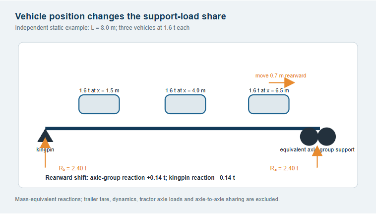
Independent mass-equivalent reactions. Trailer tare, dynamic effects, tractor axle loads and axle-to-axle sharing are excluded.
Why Must Loading Position and Road-Transport Position Be Checked Separately?
During loading, the rear ramps are deployed on the ground and some deck sections are at their loading angles. In road-transport position, the ramps are stowed, adjustable decks are positioned and locked, and every vehicle should be at its final parking and restraint position. Once the structural state changes, the vehicle envelope and complete transport envelope need another check.
The loading site needs sufficient longitudinal working space. Ground conditions and tractor position should follow the relevant equipment procedure. The UK HSE guidance for car transporters says risk assessment should consider the vehicle category, transporter design and loading site, with particular attention to upper-deck work and fall risks.
After loading and before road transport, check:
- deck sections, ramps and locking devices are in their specified transport positions;
- final clearances remain between each vehicle, the decks, adjacent vehicles and moving equipment;
- vehicle restraints suit the tyres, vehicle and platform position;
- loaded height, width, combination length and axle loads; and
- the dimension, mass and access conditions for the destination country and actual route.
Deck pinning, hydraulic operation, personnel positions, vehicle restraint and stop conditions should follow the documents for the actual equipment and operator. The calculations in this article explain matching relationships; they do not replace the operating manual for a specific model.
Africa does not use one set of country, port or route limits. A loaded height that works on one route cannot establish the same condition in another country or on another route.
How Can Actual Vehicle Data Be Applied to a CHENLU Car Carrier Configuration?
Start with a representative vehicle mix. Include the lowest vehicle, the longest wheelbase, the tallest SUV and the heavier vehicles expected in service. For multi-stop work, include the real unloading order as well.
| Input data | Matching work | Required result |
| Vehicle length, width, height, wheelbase, overhangs and lowest point | Check the ramp foot, crest, deck transitions and final vehicle envelope | Vehicle positions and the complete loading path |
| Roof accessories and local projections | Check effective deck clearance at critical longitudinal positions | Deck settings and local-clearance record |
| Vehicle mass and centre-of-gravity basis | Calculate kingpin, trailer axle-group and relevant tractor axle loads | Load distribution for each arrangement |
| Tractor connection state and loading-site conditions | Recheck the real ramp path and ramp-to-ground contact | Loading state and applicable site boundary |
| Destination, route and unloading sequence | Check transport envelope and each intermediate state | Final transport layout and multi-stop unloading sequence |
For the CHENLU special-purpose semi-trailer range, final conditions should follow the drawing and configuration data for the selected model together with the actual vehicle list. The result is more than a “multi-vehicle car carrier” label. It is a connected geometry and load case from vehicle entry and deck positioning through road transport and multi-stop unloading.
Frequently Asked Questions
What Ramp Angle Is Suitable for a Car Carrier Trailer?
There is no single angle for every vehicle and carrier. Check front overhang, the lowest point, wheelbase, approach angle, breakover angle, departure angle and the local transitions at the ramp foot and crest. The 10.1° and 8.3° values above are independent geometric examples. The 7° figure in the Hyundai GLOVIS manual applies only within that manual’s operating system.
Can Minimum Ground Clearance Alone Show Whether a Vehicle Will Scrape?
Ground clearance needs to be used with wheelbase, front and rear overhang, and the longitudinal position of the lowest point. Two vehicles with the same minimum clearance may first touch at the front, the middle of the wheelbase or the rear.
How Much Clearance Is Needed Between Car Carrier Decks?
The required space depends on the actual parked angle, the highest point of the vehicle, local structural intrusion, vehicle and deck movement, and the applicable operating procedure. Measure effective clearance at each critical longitudinal position. The approximately 102 mm roof clearance in the Hyundai GLOVIS manual applies to that manual’s scope; it is not a universal figure.
If a Vehicle Can Drive Onto the Deck, Is It Ready for Transport?
Driving onto the deck checks only part of the loading path. In transport position, also check deck clearance, deck positioning and locking, vehicle restraint, loaded height, and the loads at the kingpin, trailer axle group and tractor axles.
Can the Five-Sedan Example on the CHENLU Page Be Replaced With Five SUVs?
No direct substitution can be assumed. Vehicle count depends on the actual lengths, heights, masses and deck layout. The three-SUV-plus-one-sedan arrangement is another example on that page. A new vehicle mix still needs its own layout and load check.