A truck bracket rarely fails because it looked too thin in a product photo. Failures begin where road loads, installation variation, water, grit, and heat concentrate: a sharp bend, an unsupported tab, a weld toe, a water-holding pocket, or a fastener that shifts load into sheet metal never designed to carry it.
Designing a durable accessory requires more than making the part fit one truck in a workshop. The bracket, tray, guard, enclosure, or mount must tolerate vibration, payload changes, temperature cycles, corrosion exposure, and repeated service. The manufacturing drawing should translate those conditions into geometry and inspection that a fabricator can control.
Map the Load Path Before Drawing the Bracket
Start with what the accessory carries and where that force enters the vehicle. A light, compressor, battery box, step, storage system, or underbody guard creates different static and dynamic loads. Identify the attachment points, the direction of likely impact, and what happens if one fastener loosens.
Avoid treating the thickest visible section as the load path. Force may travel through a small flange, a slot edge, or the heat-affected area beside a weld. Sketch the path from the accessory through the bracket and fasteners into the vehicle structure. Mark every abrupt change in stiffness.
Design the Flat Pattern and Bends Together
Sheet metal parts begin as blanks but gain stiffness through bends, beads, hems, ribs, and formed returns. A small change in flange length or bend position can affect fastener access, tool clearance, coating coverage, and assembly.
When sourcing custom sheet metal fabrication, provide the 3D model and a controlled drawing that identifies material, thickness, bend direction, critical interfaces, finish, and datums. Let the fabricator generate or review the flat pattern using the intended tooling and material behavior rather than locking in an unverified developed length.
Place holes and slots with bending in mind. Features too close to a bend may distort, and a flange that is easy to model may be difficult to form or inspect. If a slotted hole is meant to absorb vehicle-to-vehicle variation, specify the installation range and the surface that locates the part after adjustment.
Use Geometry to Manage Vibration
Vibration problems are often stiffness problems. Long unsupported tabs, concentrated masses, and abrupt corners can amplify movement. Add support where it closes the load path, not simply where space is available.
Ribs and returns can increase stiffness without adding a separate heavy plate. Generous internal radii reduce stress concentration and improve forming consistency. Transitions should be smooth where a narrow arm meets a wide base. If a crack would create a safety issue, review the feature and validation plan with an engineer qualified for the application.
Fasteners also affect vibration. Define clamp surfaces, washer or flange requirements, torque strategy, locking method, and access for installation. A slot that helps assembly can allow motion if the joint does not develop and maintain adequate clamp load.
Treat Welded Joints as Designed Features
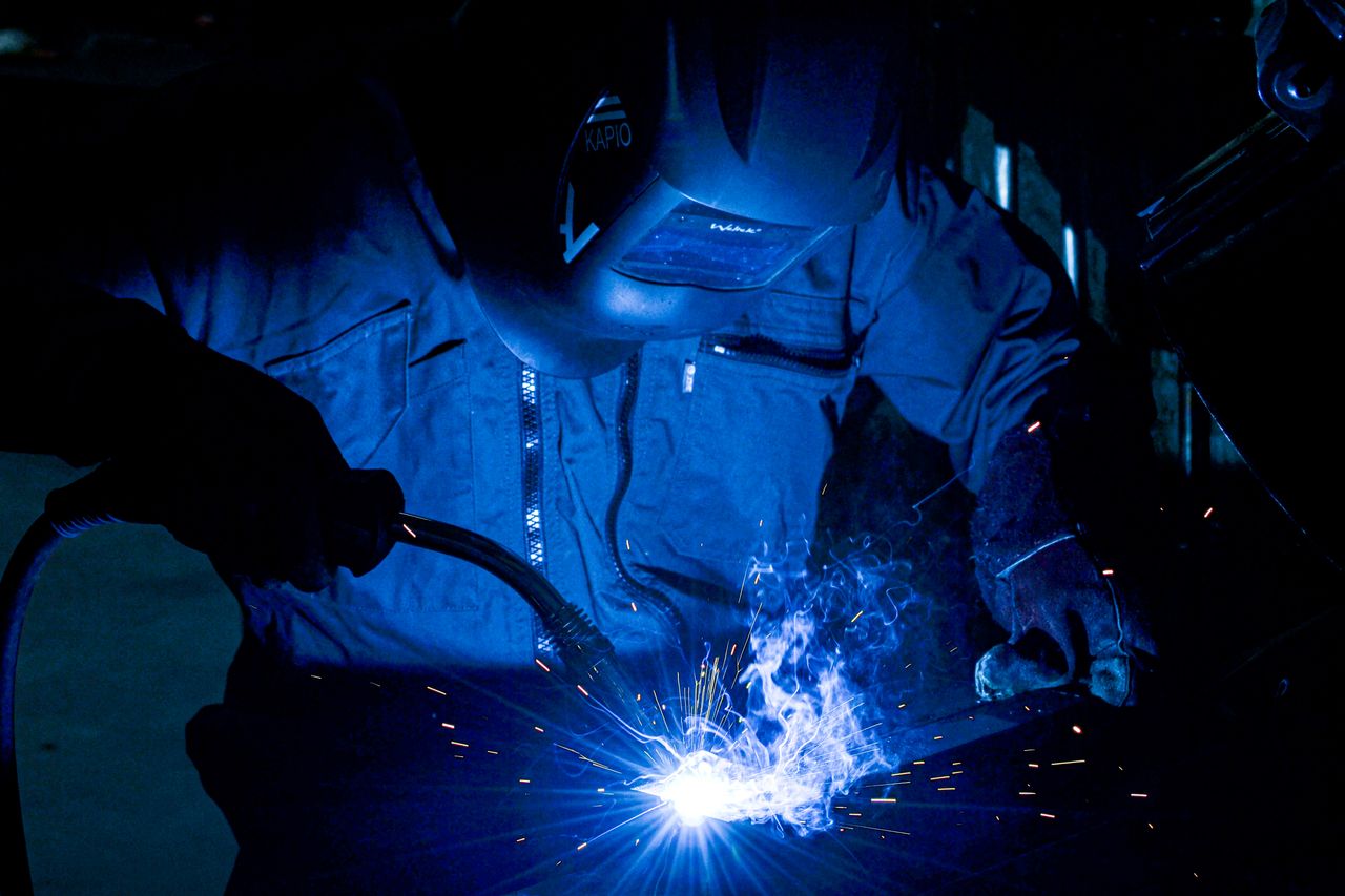
Weld symbols alone do not guarantee a durable assembly. Joint geometry must provide access, fit-up, and a repeatable path for heat. Gaps caused by loose part tolerances force the welder to compensate, increasing distortion and variation.
For truck accessories, broader automotive sheet metal fabrication considerations include joint function, weld location and extent, acceptable appearance, and the dimensions that must be checked after welding. The supplier should review whether the selected process can reach the joint and whether fixtures can hold the assembly without hiding critical areas.
Avoid placing a weld termination at the highest-stress corner when geometry allows a better transition. Do not grind welds for appearance without considering the remaining section and fatigue behavior. If a weld must be dressed, specify the functional and cosmetic acceptance condition rather than relying on “smooth” as the entire instruction.
Design Out Water and Grit Pockets
Truck accessories operate in rain, mud, road spray, dust, and deicing environments. Horizontal pockets, overlapping seams, and upward-facing channels can hold water and abrasive debris. Coating cannot protect an inaccessible crevice forever if the geometry continually retains contamination.
Provide drainage at the installed orientation, not just the drawing orientation. Check whether a drain remains open after welding and coating. Allow for cleaning where the accessory blocks the vehicle’s original wash path.
Mixed materials and contact with the vehicle can also change corrosion behavior. Select materials, coatings, isolation methods, and fasteners as a system. Define cosmetic zones, masked areas, threads, mating surfaces, and how exposed areas will be protected.
Validate on the Vehicle, Then Validate on the Road
A dimensional inspection should confirm the bracket is made to the drawing, but the vehicle reveals whether the drawing captured reality. Install samples on more than one representative vehicle when tolerances or model variations matter. Record any forcing, drilling, prying, or fastener substitution required during installation.
Road validation should represent the accessory’s use. Check vibration, noise, fastener retention, contact with adjacent components, drainage, coating damage, and deformation after realistic loading. Record the part revision, vehicle, load, installation method, test duration, and any failure location.
Conclusion
Durable truck accessories come from controlled load paths, formable geometry, designed welds, drainage, compatible finishes, and realistic validation. Thickness is only one variable. Before production, review the bracket as an installed system with the fabricator, then test the critical interfaces on representative vehicles and real road conditions.
FAQ
Should a truck bracket simply be made thicker if it cracks?
Not automatically. Find the load path, stress concentration, joint movement, material condition, and failure mode first. Extra thickness can move the problem elsewhere.
Are slots better than round holes for vehicle fit-up?
Slots can accommodate variation but may permit movement if clamp load and locating surfaces are inadequate. Design the complete joint.
When should an accessory be welded instead of bolted?
The choice depends on load, serviceability, heat effects, installation, corrosion protection, and the vehicle interface. Many assemblies use both methods for different functions.
Why measure a bracket after welding?
Heat input and fixture restraint can change alignment. Post-weld inspection verifies the interfaces the installer actually receives.
What should a road-validation report include?
Record the vehicle, accessory revision, installation, fasteners, loads, route or test conditions, duration, observations, and post-test inspection results.